SKU: OT6682 Αριθμός είδους: XR791 EAN: 8720828223468

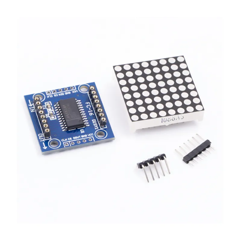
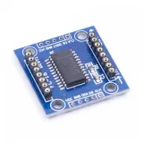
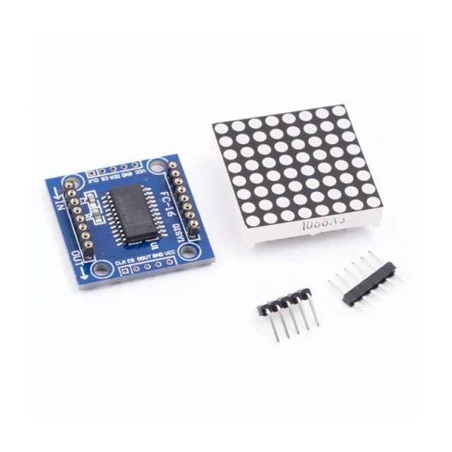
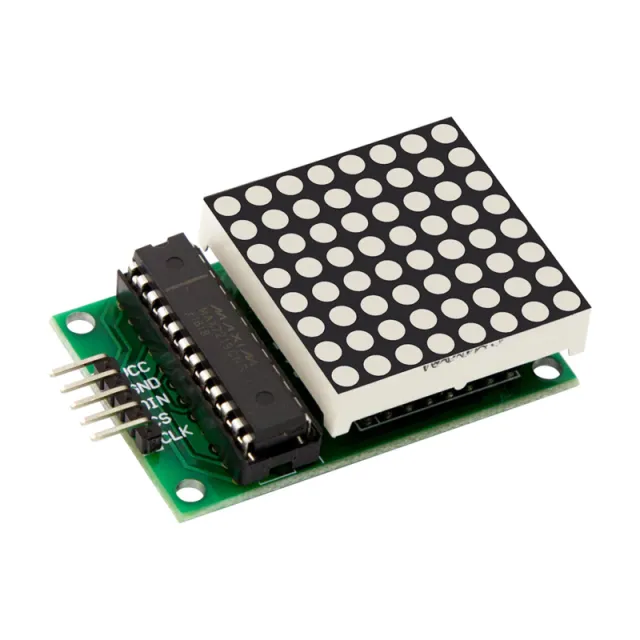
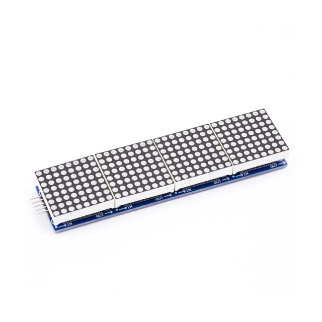
Το MAX7219 είναι ένα IC που χρησιμοποιείται για τον έλεγχο LED πάνελ με κοινή κάθοδο, οθονών 7 τμημάτων και δεικτών στάθμης που επικοινωνούν μέσω της διεπαφής SPI. Αυτή η πλακέτα διαθέτει οθόνη LED dot matrix 8x8. Πολλαπλές μονάδες μπορούν να συνδεθούν σε αλυσίδα χρησιμοποιώντας συνδέσεις header.
Προδιαγραφές:
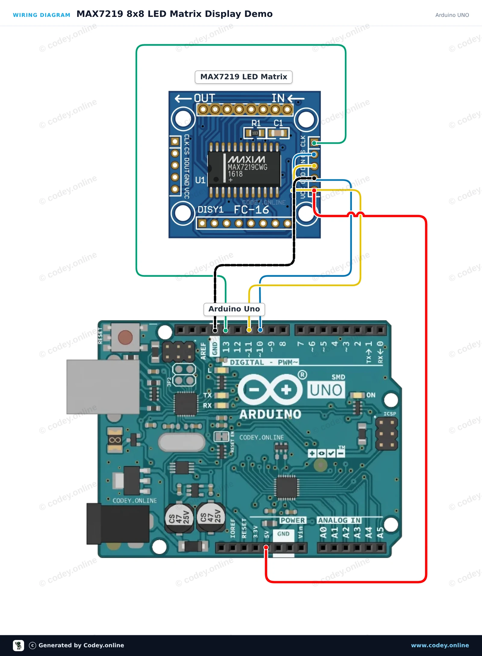
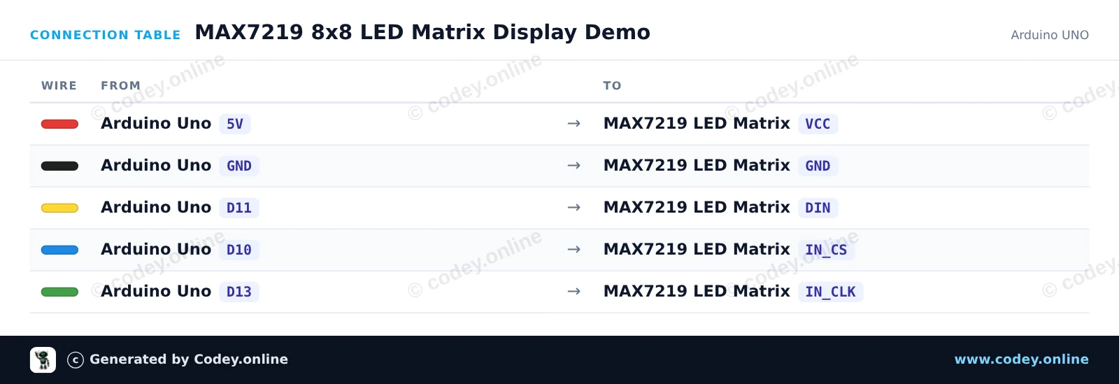
Έτσι συνδέεις το Μονάδα LED Matrix MAX7219 Πράσινη σε ένα Arduino UNO ή ESP32, με ένα παράδειγμα sketch που μπορείς να ανεβάσεις αμέσως.
Αυτό το project δείχνει πώς να ελέγξετε μια μήτρα LED 8x8 MAX7219 με ένα Arduino Uno. Το sketch αρχικοποιεί την οθόνη και εναλλάσσει την εμφάνιση μιας καρδιάς, ενός χαμογελαστού προσώπου και μιας κινούμενης εικόνας ενός τετραγώνου που μεγαλώνει.
/*
 * ==================================================================
 *  Generated by Codey.online  —  https://www.codey.online
 * ==================================================================
 *  Project   : MAX7219 8x8 LED Matrix Display Demo
 *  Board     : Arduino UNO (arduino:avr:uno)
 *  Parts     : LED Matrix Module MAX7219
 *  Libraries : LedControl 1.0.6
 *
 *  Codey Online is an AI-powered browser IDE for Arduino and ESP32.
 *  Describe your project and Codey writes the code, draws the wiring
 *  diagram and uploads it to your board, straight from the browser.
 *  This code is free to use, modify and share, without warranty.
 * ==================================================================
 */

#include <LedControl.h>

const int DIN_PIN = 11;
const int CS_PIN  = 10;
const int CLK_PIN = 13;

LedControl lc = LedControl(DIN_PIN, CLK_PIN, CS_PIN, 1);

const byte HEART[8] = {
  B00000000,
  B01100110,
  B11111111,
  B11111111,
  B11111111,
  B01111110,
  B00111100,
  B00011000
};

const byte SMILE[8] = {
  B00111100,
  B01000010,
  B10100101,
  B10000001,
  B10100101,
  B10011001,
  B01000010,
  B00111100
};

void displayPattern(const byte pattern[8]) {
  for (int row = 0; row < 8; row++) {
    lc.setRow(0, row, pattern[row]);
  }
}

void setup() {
  Serial.begin(115200);
  Serial.println(F("MAX7219 LED Matrix Demo"));

  lc.shutdown(0, false);  // Wake up display
  lc.setIntensity(0, 8);   // Set brightness (0-15)
  lc.clearDisplay(0);
}

void loop() {
  // Show Heart
  displayPattern(HEART);
  delay(1500);

  // Show Smile
  displayPattern(SMILE);
  delay(1500);

  // Dot scan animation
  lc.clearDisplay(0);
  for (int row = 0; row < 8; row++) {
    for (int col = 0; col < 8; col++) {
      lc.setLed(0, row, col, true);
      delay(20);
    }
  }
  delay(500);
  lc.clearDisplay(0);
  delay(300);
}Απαραίτητες βιβλιοθήκες: LedControl 1.0.6
Wiring diagram and example code generated by Codey.online — https://www.codey.online
Αυτό το έργο χρησιμοποιεί τη hardware SPI διεπαφή του ESP32 για να ελέγξει μια μήτρα LED MAX7219 8x8 χωρίς να απαιτούνται εξωτερικές βιβλιοθήκες. Το sketch αρχικοποιεί την οθόνη και εναλλάσσεται ανάμεσα στην εμφάνιση ενός χαμογελαστού προσώπου, ενός εικονιδίου καρδιάς και ενός animation σάρωσης γραμμών.

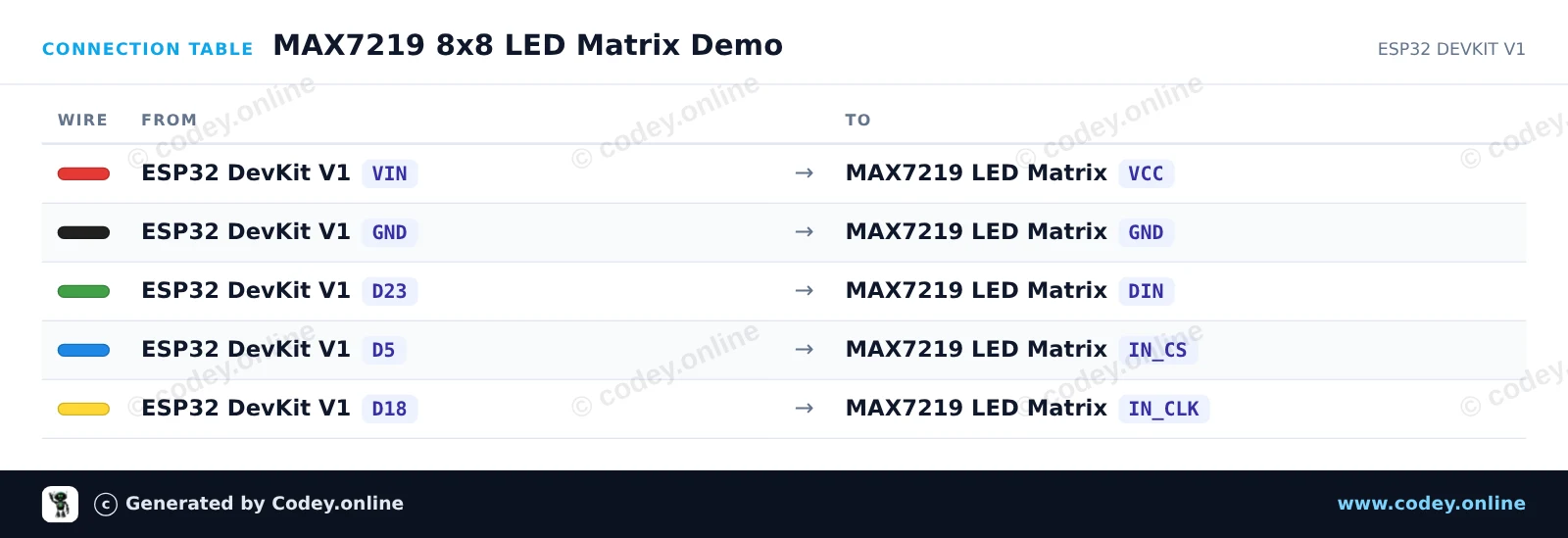
/*
 * ==================================================================
 *  Generated by Codey.online  —  https://www.codey.online
 * ==================================================================
 *  Project   : MAX7219 8x8 LED Matrix Demo
 *  Board     : ESP32 DEVKIT V1 (esp32:esp32:esp32doit-devkit-v1)
 *  Parts     : LED Matrix Module MAX7219
 *  Libraries : none (built-in)
 *
 *  Codey Online is an AI-powered browser IDE for Arduino and ESP32.
 *  Describe your project and Codey writes the code, draws the wiring
 *  diagram and uploads it to your board, straight from the browser.
 *  This code is free to use, modify and share, without warranty.
 * ==================================================================
 */

#include <SPI.h>

const int CS_PIN = 5;

// MAX7219 register addresses
const byte REG_NOOP   = 0x00;
const byte REG_DIGIT0 = 0x01;
const byte REG_DECODE = 0x09;
const byte REG_INTEN  = 0x0A;
const byte REG_SCAN   = 0x0B;
const byte REG_SHUT   = 0x0C;
const byte REG_TEST   = 0x0F;

// 8x8 Bitmaps
const byte SMILE[8] = {
  0b00111100,
  0b01000010,
  0b10100101,
  0b10000001,
  0b10100101,
  0b10011001,
  0b01000010,
  0b00111100
};

const byte HEART[8] = {
  0b00000000,
  0b01100110,
  0b11111111,
  0b11111111,
  0b11111111,
  0b01111110,
  0b00111100,
  0b00011000
};

void max7219Send(byte reg, byte data) {
  digitalWrite(CS_PIN, LOW);
  SPI.transfer(reg);
  SPI.transfer(data);
  digitalWrite(CS_PIN, HIGH);
}

void clearDisplay() {
  for (byte i = 1; i <= 8; i++) {
    max7219Send(i, 0x00);
  }
}

void displayBitmap(const byte bitmap[8]) {
  for (byte i = 0; i < 8; i++) {
    max7219Send(i + 1, bitmap[i]);
  }
}

void setup() {
  Serial.begin(115200);
  pinMode(CS_PIN, OUTPUT);
  digitalWrite(CS_PIN, HIGH);

  // Initialize hardware SPI (SCK=18, MISO=19, MOSI=23, SS=5)
  SPI.begin(18, 19, 23, CS_PIN);

  // Configure MAX7219 registers
  max7219Send(REG_TEST, 0x00);   // Normal operation (display test off)
  max7219Send(REG_SCAN, 0x07);   // Scan all 8 digits/rows
  max7219Send(REG_DECODE, 0x00); // Raw matrix mode (no BCD decoding)
  max7219Send(REG_INTEN, 0x04);  // Medium brightness (0x00 to 0x0F)
  max7219Send(REG_SHUT, 0x01);   // Normal operation (wake up)
  clearDisplay();

  Serial.println("MAX7219 LED Matrix ready!");
}

void loop() {
  // Show Smiley Face
  displayBitmap(SMILE);
  delay(2000);

  // Show Heart Icon
  displayBitmap(HEART);
  delay(2000);

  // Row scan animation
  clearDisplay();
  for (byte r = 1; r <= 8; r++) {
    max7219Send(r, 0xFF);
    delay(100);
    max7219Send(r, 0x00);
  }
}Wiring diagram and example code generated by Codey.online — https://www.codey.online





 English
  Nederlands
  Frans
Frans  Deutsch
  Italiano
  Español
  Suomi
Suomi  Polski
  Dansk
Dansk  Български
  Čeština
  Hrvatski
  Svenska
  Aileen