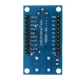
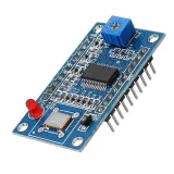
SKU: OT3459 Αριθμός είδους: NA416 EAN: 8720618690838

Οι γεννήτριες σήματος/λειτουργίας είναι εξαιρετικά χρήσιμες από RF έως ενσωματωμένη λογική, αλλά συνήθως δεν είναι και τόσο οικονομικές.
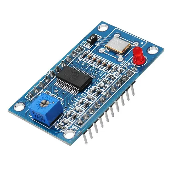
Καλά νέα: με αυτήν τη μονάδα AD9850 DDS μπορείτε, με λίγη συναρμολόγηση, να φτιάξετε τη δική σας ευέλικτη, λειτουργική και εύχρηστη γεννήτρια συχνοτήτων Arduino!
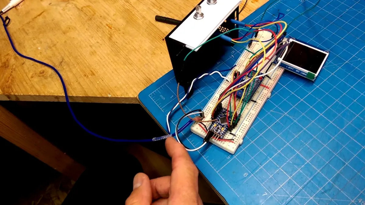
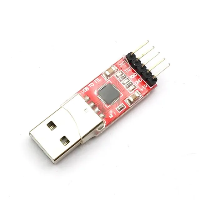
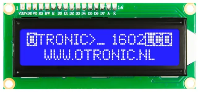
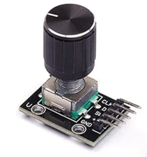
Με οθόνη LED, περιστροφικό ποτενσιόμετρο και ένα Arduino μπορείτε να φτιάξετε μια εύκολη στη χρήση, αυτόνομη γεννήτρια σήματος. (Μην ξεχάσετε να προμηθευτείτε έναν CP2102 USb naar TTL Serial Converter αν δεν έχετε ήδη έναν)
Μπορείτε επίσης να επιλέξετε να τη συνδυάσετε μόνο με Arduino Uno σε breadboard.
Μια εντελώς διαφορετική προσέγγιση είναι να χρησιμοποιήσετε αυτήν τη μονάδα για να φτιάξετε το δικό σας Software Defined Radio (SDR).
Με λίγα λόγια, μια όμορφη μονάδα για να ξεκινήσετε!
Χαρακτηριστικά:
ΕΦΑΡΜΟΓΕΣ:
Με την αναπαραγωγή φορτώνεται το βίντεο από το YouTube.
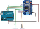
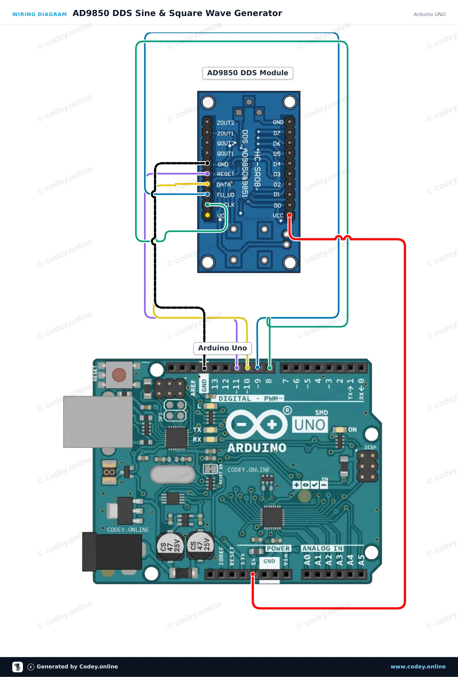
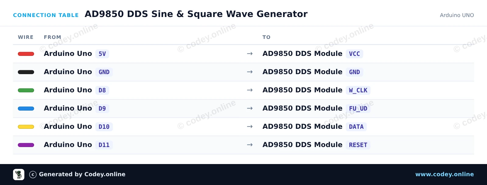
Έτσι συνδέεις το AD9850 DDS Μονάδα Γεννήτριας Σήματος σε ένα Arduino UNO ή ESP32, με ένα παράδειγμα sketch που μπορείς να ανεβάσεις αμέσως.
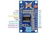
Αυτό το έργο ελέγχει μια μονάδα AD9850 DDS μέσω σειριακής διεπαφής 4 καλωδίων για τη δημιουργία ακριβών συχνοτήτων ημιτονοειδούς και τετραγωνικού κύματος. Το Arduino αρχικοποιεί τη μονάδα DDS και αλλάζει περιοδικά τη συχνότητα εξόδου μεταξύ 1 kHz, 10 kHz και 100 kHz. Συνδέστε έναν παλμογράφο ή έναν μετρητή συχνότητας στο ZOUT1 (ημιτονοειδές κύμα) ή στο QOUT1 (τετραγωνικό κύμα) για να ελέγξετε το σήμα εξόδου.
/*
 * ==================================================================
 *  Generated by Codey.online  —  https://www.codey.online
 * ==================================================================
 *  Project   : AD9850 DDS Sine & Square Wave Generator
 *  Board     : Arduino UNO (arduino:avr:uno)
 *  Parts     : AD9850 DDS Signal Generator Module
 *  Libraries : none (built-in)
 *
 *  Codey Online is an AI-powered browser IDE for Arduino and ESP32.
 *  Describe your project and Codey writes the code, draws the wiring
 *  diagram and uploads it to your board, straight from the browser.
 *  This code is free to use, modify and share, without warranty.
 * ==================================================================
 */

const int PIN_W_CLK = 8;
const int PIN_FQ_UD = 9;   // Labeled FU_UD on module
const int PIN_DATA  = 10;
const int PIN_RESET = 11;

const unsigned long AD9850_REF_CLOCK = 125000000UL; // 125 MHz reference oscillator

void pulsePin(int pin) {
  digitalWrite(pin, HIGH);
  delayMicroseconds(1);
  digitalWrite(pin, LOW);
  delayMicroseconds(1);
}

void ad9850Reset() {
  digitalWrite(PIN_RESET, HIGH);
  delayMicroseconds(1);
  digitalWrite(PIN_RESET, LOW);
  delayMicroseconds(1);
  pulsePin(PIN_W_CLK);
  pulsePin(PIN_FQ_UD);
}

void ad9850SetFrequency(double freqHz) {
  // Calculate 32-bit tuning word: (freq * 2^32) / ReferenceClock
  uint32_t tuningWord = (uint32_t)((freqHz * 4294967296.0) / (double)AD9850_REF_CLOCK);

  // Transmit 32-bit frequency tuning word (LSB first)
  for (int i = 0; i < 32; i++) {
    digitalWrite(PIN_DATA, (tuningWord >> i) & 0x01);
    pulsePin(PIN_W_CLK);
  }

  // Transmit 8 control/phase bits (all 0 for normal operation)
  for (int i = 0; i < 8; i++) {
    digitalWrite(PIN_DATA, LOW);
    pulsePin(PIN_W_CLK);
  }

  // Latch the updated frequency into the DDS core
  pulsePin(PIN_FQ_UD);
}

void setup() {
  pinMode(PIN_W_CLK, OUTPUT);
  pinMode(PIN_FQ_UD, OUTPUT);
  pinMode(PIN_DATA, OUTPUT);
  pinMode(PIN_RESET, OUTPUT);

  digitalWrite(PIN_W_CLK, LOW);
  digitalWrite(PIN_FQ_UD, LOW);
  digitalWrite(PIN_DATA, LOW);
  digitalWrite(PIN_RESET, LOW);

  Serial.begin(115200);
  while (!Serial) {
    ;
  }

  Serial.println(F("AD9850 DDS Generator Initialized"));
  ad9850Reset();
}

void loop() {
  const double testFrequencies[] = {1000.0, 10000.0, 100000.0};

  for (int i = 0; i < 3; i++) {
    double freq = testFrequencies[i];
    ad9850SetFrequency(freq);
    Serial.print(F("Output frequency set to: "));
    Serial.print(freq);
    Serial.println(F(" Hz"));
    delay(3000);
  }
}Wiring diagram and example code generated by Codey.online — https://www.codey.online
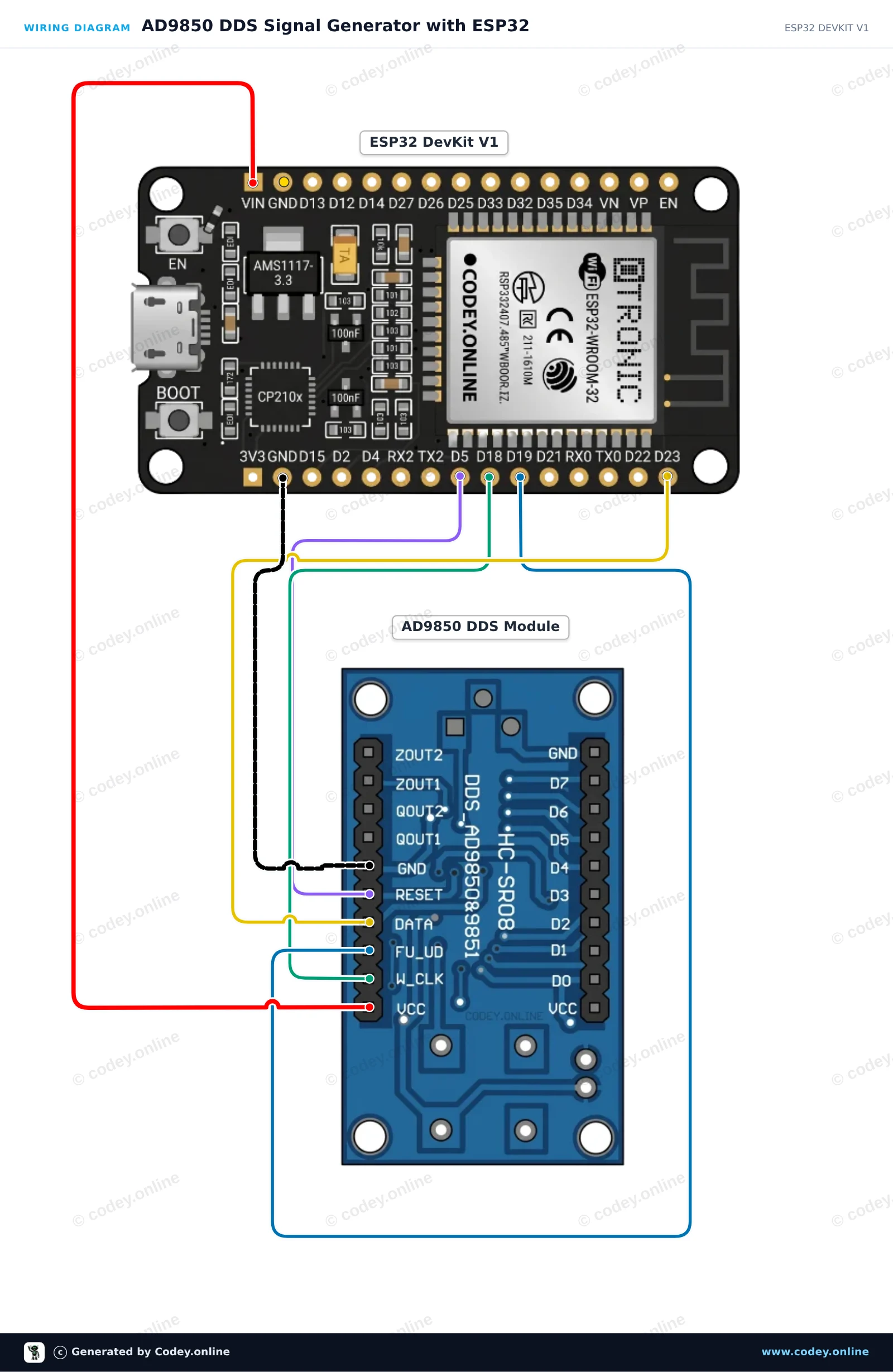
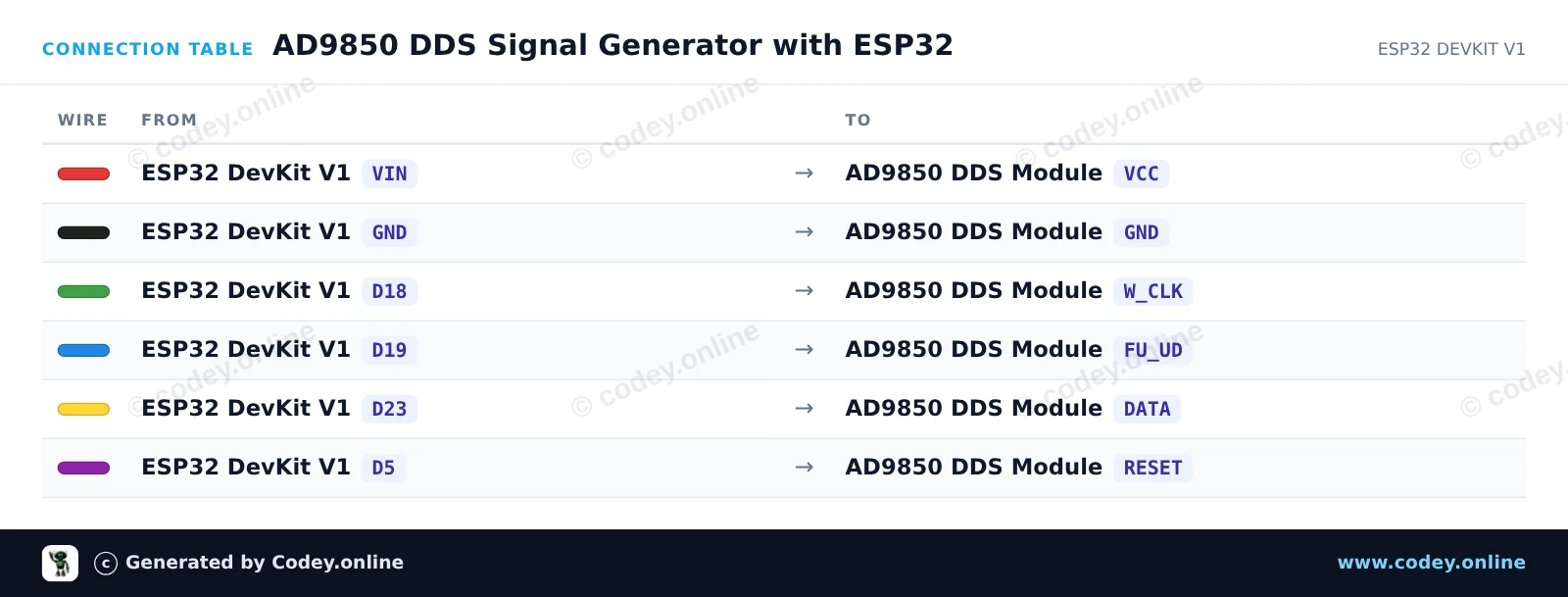
Αυτό το έργο παράγει ακριβή ημιτονοειδή και τετραγωνικά σήματα χρησιμοποιώντας τη μονάδα DDS AD9850 που ελέγχεται από ένα ESP32. Το sketch προχωρά σε μια ακολουθία συχνοτήτων (1 kHz, 10 kHz, 100 kHz και 1 MHz) κάθε 3 seconds. Συνδέστε έναν παλμογράφο ή έναν μετρητή συχνότητας στο ZOUT1 για ημιτονοειδές σήμα ή στο QOUT1 για τετραγωνική έξοδο.
/*
 * ==================================================================
 *  Generated by Codey.online  —  https://www.codey.online
 * ==================================================================
 *  Project   : AD9850 DDS Signal Generator with ESP32
 *  Board     : ESP32 DEVKIT V1 (esp32:esp32:esp32doit-devkit-v1)
 *  Parts     : AD9850 DDS Signal Generator Module
 *  Libraries : none (built-in)
 *
 *  Codey Online is an AI-powered browser IDE for Arduino and ESP32.
 *  Describe your project and Codey writes the code, draws the wiring
 *  diagram and uploads it to your board, straight from the browser.
 *  This code is free to use, modify and share, without warranty.
 * ==================================================================
 */

// AD9850 DDS Signal Generator Demo on ESP32
const int W_CLK_PIN = 18;
const int FU_UD_PIN = 19;
const int DATA_PIN  = 23;
const int RESET_PIN = 5;

// 125 MHz reference clock crystal on board
const double REF_CLK = 125000000.0;

const double testFrequencies[] = {1000.0, 10000.0, 100000.0, 1000000.0};
const int numFrequencies = sizeof(testFrequencies) / sizeof(testFrequencies[0]);
int currentFreqIndex = 0;

void pulseHigh(int pin) {
  digitalWrite(pin, HIGH);
  delayMicroseconds(1);
  digitalWrite(pin, LOW);
  delayMicroseconds(1);
}

void resetAD9850() {
  pulseHigh(RESET_PIN);
  pulseHigh(W_CLK_PIN);
  pulseHigh(FU_UD_PIN); // Enable serial load mode
}

void sendFrequency(double frequency) {
  uint32_t tuningWord = (uint32_t)((frequency * 4294967296.0) / REF_CLK);

  // Send 32-bit frequency tuning word (LSB first)
  for (int i = 0; i < 32; i++) {
    digitalWrite(DATA_PIN, (tuningWord >> i) & 0x01);
    pulseHigh(W_CLK_PIN);
  }

  // Send 8 control/phase bits (0x00 for 0 phase offset)
  for (int i = 0; i < 8; i++) {
    digitalWrite(DATA_PIN, LOW);
    pulseHigh(W_CLK_PIN);
  }

  // Latch new frequency to output
  pulseHigh(FU_UD_PIN);
}

void setup() {
  Serial.begin(115200);
  delay(500);
  Serial.println("AD9850 DDS Signal Generator Initializing...");

  pinMode(W_CLK_PIN, OUTPUT);
  pinMode(FU_UD_PIN, OUTPUT);
  pinMode(DATA_PIN,  OUTPUT);
  pinMode(RESET_PIN, OUTPUT);

  digitalWrite(W_CLK_PIN, LOW);
  digitalWrite(FU_UD_PIN, LOW);
  digitalWrite(DATA_PIN,  LOW);
  digitalWrite(RESET_PIN, LOW);

  resetAD9850();
  Serial.println("AD9850 ready!");
}

void loop() {
  double freq = testFrequencies[currentFreqIndex];
  sendFrequency(freq);

  Serial.print("Output frequency set to: ");
  Serial.print(freq, 0);
  Serial.println(" Hz");

  currentFreqIndex = (currentFreqIndex + 1) % numFrequencies;
  delay(3000);
}Wiring diagram and example code generated by Codey.online — https://www.codey.online





 English
  Nederlands
  Frans
Frans  Deutsch
  Italiano
  Español
  Suomi
Suomi  Polski
  Dansk
Dansk  Български
  Čeština
  Hrvatski
  Svenska
  Aileen